Achieving the realistic look of desert sand on a layout or diorama can be a fun and rewarding project. There are a...

Cart 0 Product Products (empty)
No products
Free shipping! Shipping
£ 0.00 Total
Product successfully added to your shopping cart
Quantity
Total
There are 0 items in your cart. There is 1 item in your cart.
Total products (tax incl.)
Total shipping (tax excl.) Free shipping!
Total (tax incl.)
Search Tips
Tips categories
Latest Tips
-
 How can I best achieve the look of desert sand on a layout or diorama ?Read more
 -
 What are my options for motorising points on an N Gauge layout?Read more
There are several options for motorising points on an N Gauge layout. Here are some of the most common methods:...
-
 How can I best model a tram system in an urban setting ?Read more
Modelling a tram system in an urban setting can add a unique and realistic touch to a model railway layout. Trams are...
-
 What type of paint is needed to weather models?Read more
When it comes to weathering models successfully, a mixture of techniques, research, products and equipment are all...
-
 What does AFV mean in military scale modelling?Read more
AFV stands for Armoured Fighting Vehicle. These versatile military machines come in many shapes, sizes and forms but...

What is a dropper wire?
When using a bus wire (shared common wire) to distribute power around your layout, you will inevitably have to tap into the wire at various locations to install small stretches of additional wire to connect the main bus wire with the components or sections of track that you wish to supply power to. It is these small stretches of connecting wires that are known as the dropper wires.
Dropper wires can be thinner than the main bus wire and only need to be thick enough to carry the amount of current needed to power the component in question. They can be soldered directly into the main bus wire but you should always be careful to install any resistors that are required for the protection of the components being installed.
Another consideration when installing dropper wires is that the bus wire you are tapping into is carrying the correct type of current for the intended component because an AC power supply will likely cause damage to any components that are intended to be operated by DC.
Click here to receive the tips weekly in your mailbox. You can unsubscribe at any time.
Related products

5 x Small Type 3Amp 12 Way Connector Blocks
Price: £ 4.505 x Small Type 3Amp 12 Way Connector Blocks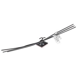
Tidy Wire Kit
Price: £ 9.50Adhesive-backed Wire Tie Mounts secure cables and Wire Ties bundle cables...
Related posts
-
 What scale is Hornby?Hornby model railways are OO Scale or 1/76th that is 4 millimetres to the foot (12 inches). It runs on a track with...
 - How to weight my model so it does not tip?For wargaming figures, a small coin or washer glued to the under side of the base will usually to do the job. This...
- Is Bachmann compatible with Hornby?Yes, any OO scale loco, wagon or coach will work on any OO scale track, regardless of brand. Couplings are also...
- What are the model railway eras?According to Bachmann, as it states in their catalogue there are 9 eras. As they say in their catalogue this is not...
- Can a "DCC ready" train be used on analogue?Yes, you can use a DCC ready train on your analogue layout. DCC ready just means that the train has been factory...